PRE COMMISSIONING TEST FOR CURRENT TRANSFORMER
Purpose
This procedure is prepared to carry out various pre commissioning for current transfromer tests to be conducted in systematic manner for CT to ensure the healthiness and performance of the equipment
Scope
This procedure covers the Pre commissioning test for CT as for the following
- Insulation Resistance Test
- Secondary Winding resistance test
- Polarity test
- Ratio test
- Magnetizing Curve test
- Capacitance and Tan Delta Measurement Test
Pre-Testing Checks
-
- Check out the working condition of ELCB(30 mA)
- Check the insulation of power cable for equipment
- Ensure proper earthing and rubber mats available at the work
- Calibrated Testing equipment should be used and calibration reports available with engineers for the same
- Check out the insulates hand tools available with the technician
- Ensure the Healthiness of the test leads (Check for any insulation Damages)
- Ensure appropriate PPE’s available at sites
- Unused spare secondary cores terminals should be shorted in CT JB
- Physically check for CT for any damage, oil leakage
Resources – Tools and Equipment Required
- Continuity Test
- Multimeter with leads
2. For Insulation Resistance measurement Test(IR Test)
- Test Leads
- 500 V, 5000 V Insulation Tester
- Insulated Hand Tools
3. Winding resistance test
- Multimeter with leads
4. Polarity test
- 9V battery
- Galvano meter
- Connecting leads
5. Ratio test
- Variac / auto transformer
- Loading transformer
- Welding cable
- Clamp meter
- Current leakage tester
- Connecting leads
6. Magnetizing curve test
- Single phase variac 0-230 V,28 A
- Step-up transformer(230 V/5000 V/2 KVA)
- Multimeter
- Current leakage tester
- Connecting leads
7. Capacitance and Tan Delta Measurement Test
- Tan Delta kit
- Connecting leads
Pre-Testing
Insulation Resistance (IR) Test
Primary to Earth:
- Connect the Earth lead of the 5000 V IR kit to the earth Terminal
- Connect HV lead of the 5000 V IR kit to either P1 or P2 of the current Transformer
- Switch “ON” the 5000 V IR kit and Select the required voltage range in IR kit
- press the Test button take down the readings
- Switch “OFF” the IR kit
Primary to Secondary:
- Connect HV lead of the5000V IR kit to either P1 or P2 of the current Transformer
- Connect Earth lead of the 5000V IR kit to either S1 or S2 of the current Transformer
- Switch “ON” the 5000V IR kit and Select the required voltage range in IR kit
- press the Test button take down the readings
- Switch “OFF” the IR kit
Secondary to Earth:
- Connect Earth lead of the IR kit to the earth terminal
- Connect HV lead of the IR kit to either S1 or S2 of the current Transformer
- Switch “ON” the IR kit and Select the required voltage range in IR kit
- press the Test button take down the readings
- Switch “OFF” the IR kit
Between Secondary Cores:
- Connect HV lead of the 500 V IR kit to either S1 or S2 of the current Transformer
- Connect Earth lead of the 500 V IR kit to either S1 or S2 of the other core of the current Transformer
- Switch “ON” the 500 V IR kit and Select the required voltage range in IR kit
- press the Test button take down the readings
- Switch “OFF” the 500 V IR kit
- Discharge the voltage from the CT with respect to earth
| DO’S | DON’TS |
|
|
Winding resistance test
Secondary resistance test is to verify the CT secondary winding resistance with specified one and no discontinuity in the winding. This value can be used in other calculations.
Operational sequence:
- Connect the multimeter leads to the CT secondary winding Terminals
- Note down the winding resistance value
- Repeat the above procedure for remaining cores
| DO’S | DON’Ts |
|
|
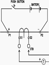
Polarity test
Description
Polarity test is to confirm the polarity marking on the CT primary and secondary and verify it is matching with drawing. More ever it is giving an idea, how to connect the secondary’s to make the protection (like directional, differential) and metering function properly.
Operational Sequence:
- Connect the secondary S1 terminal to galvanometer positive terminal and S2 to the negative terminal
- Touch the battery positive terminal to P1 in and negative terminal to the P2 terminal at the CT primary winding Terminals
- Check the deflection in the galvanometer
- It must be in clock-wise direction
| DO’S | DONT’S |
|
|
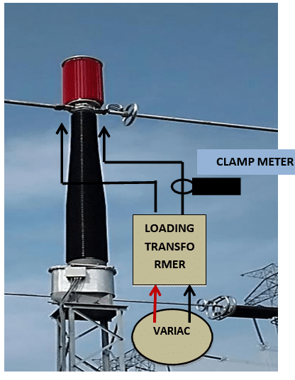
Ratio test
Description:
This test is to ensure the turn’s ratio of CT at all taps. The circuit connection shall be made as shown Figure 2. The primary current of minimum of 25% rate primary current to be injected on primary side of CT with secondary’s shorted and the secondary current can be measured and recorded for all cores
Operational sequence:
- Connect the variac and loading transformer
- Connect the loading transformer across the primary terminals(P1,P2)
- Connect the variac in A.C supply extension board with ELCB rated with 30 mA
- Inject the current across the primary terminals.
- Short all secondary windings core by wire at CT junction box
- Note down the corresponding secondary current each cores at 20 % and 40% of rated primary current
- Switch off the supply to the primary injection kit
| DO’S | DONT’S |
|
|
Excitation Current
Purpose of the Test
The magnetization test is conducted in order to see the condition of the turns of the secondary. This test gives the indications regarding the shorting of turns CT secondary winding and to establish CT characteristics as well as capability of CT.
Procedure of the test
- Apply AC voltage to the secondary winding of the CT with primary open circuit
- Vary the applied voltage from 25% of Vk to 110 % of Vk
- Measure the current drawn by the winding at each selected value is recorded
- Verify that, exciting current is less than specified at Vk/2
- This test should not be performed for metering core
- If Knee Point Voltage is not mentioned then Knee Point Current may be taken into Consideration.
| Make | Type | Sr. no. | Range | Cal. Due date |
Acceptance Criteria
- Excitation current should not be more than specified on name plate.
- 10 % increase in the voltage from 100 % to 110 %, increase in current should not be more than 50%
| DO’S | DONT’S |
|
|
Capacitance and Tan Delta Measurement Test
Purpose of the test:
- Dissipation factor / loss factor/ Tan delta is defined as the ratio of resistive components to that Of capacitive current flowing in an insulating material.
- Dissipation factor (tan delta) and capacitance measurement of bushing/winding provides an Indication of the quality and soundness of the insulation in the bushing/winding. Changes in the normal capacitance of an insulator indicate abnormal conditions such as the Presence of moisture layer, short -circuits or open circuits in the capacitance network.
Principle of the test:
The capacitance and dissipation/loss factor (Tan δ / Cos φ) measurement are made to determine the insulating condition of the Current transformer’s both winding to earth and between the windings, and to form a reference for future measurements during operating the current transformer.
Equipment for the test:
10 KV or 12 KV fully automatic Capacitance and Tan delta test kit to be used for accurate measurement and repeatability of test results
Procedure for the test
Primary to secondary
- These values of capacitance and their respective values of insulation factor (tan delta) are to be measured.
- HV line terminals connect in the primary & LV line terminals connected tan delta point of the CT
- Disconnect the earthing of the tan delta point
- These measurements are usually made at voltage of 10 kV or less, at power frequency.
For tan delta between windings, connections are to be carried out in UST
Acceptance Criteria
Tan δ for bushing (C1):
| Type of bushing | Tan δ (C1) | Capacitance | |
| % Limit | % Change/annum | % Change/annum | |
| Resin impregnated paper insulated | 0.85 | +0.04 / -0.04 | +1.0 / -1.0 |
| Oil impregnated paper insulated | 0.40 | +0.02 / -0.06 | +1.0 / -1.0 |
| DO’S | DONT’S |
|
|
Control Measures
- OCP for all test for CT is available with testing engineers
- Ensure PTW system in place for the particular bay
- Ensure all supply to the equipment is dead
- Unauthorized persons should not be allowed to enter Testing area
- More than 2Mtr height shall be used Proper working plat form or man lifter and suggested for complying with fall arrester or Full body harness
- Less than 2Mtr height shall be used standard insulated ladder
- Inspect the ladders prior to work, keep both feet below 3rd rung from top, keep one hand on ladder minimum at all times and suggested for complying with full body harness
- Barricade the testing area with warning tape
- Proper supervision, conduct job specific toolbox meeting and barricading the entire area
- Calibrated equipment shall be used
- Insulated hand tools shall be used
- Avoid joints for power cable and supply has to be taken via ELCB
- Avoid Lone working
- Use appropriate insulated hand gloves
- CT secondary side don’t keep on open condition