
Introduction to Current Transformers
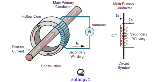
- Current transformers (CTs) are vital components in electrical systems, designed to measure alternating current (AC) by producing a reduced current proportional to the current in the circuit they are monitoring. These devices play a crucial role in ensuring the accurate measurement of electrical parameters, which is essential for various applications including system protection, metering, and maintaining overall reliability.
- CTs are particularly important in high-voltage environments where direct measurement of the primary current would be impractical or unsafe. By stepping down the high current to a lower, more manageable value, CTs enable the safe and precise monitoring of electrical systems. This proportional reduction allows for the use of standard measuring instruments, which can then provide accurate readings and ensure the appropriate response to any anomalies in the system.
- The accuracy of current transformers is paramount for the efficient operation of electrical systems. Inaccurate measurements can lead to a range of issues, from incorrect billing in metering applications to inadequate protection in fault conditions. Proper functioning of CTs ensures that protection relays and meters receive accurate data, which is crucial for triggering appropriate safety mechanisms and maintaining the integrity of the electrical infrastructure.
- Given the critical role of current transformers, rigorous testing is essential to verify their performance and reliability. Testing ensures that CTs meet the required standards and can operate effectively under various conditions. This process involves assessing the accuracy, burden, and insulation properties of the transformers to guarantee their dependable operation.
- In essence, the role of current transformers in electrical systems cannot be overstated. Their ability to provide accurate measurements is foundational to system protection, precise metering, and overall reliability. Consequently, understanding the importance of testing these devices is crucial, as it ensures the continued safety and efficiency of electrical networks.
-

Current Transformers
Types of Tests for Current Transformers
Ensuring the accuracy and reliability of current transformers (CTs) is paramount in electrical systems. To achieve this, various tests are conducted, categorized broadly into routine tests, type tests, and special tests. Each category serves a specific purpose and employs distinct methodologies tailored to evaluate different aspects of the current transformer’s performance.
Routine Tests
Routine tests are essential quality control measures performed on each current transformer manufactured. One of the fundamental routine tests is the ratio test, which verifies that the CT accurately transforms the primary current to the secondary current according to its designed ratio. This ensures the CT will function correctly in its intended application.
Another critical routine test is the polarity test. This test ensures that the connections of the primary and secondary windings are correctly oriented, which is crucial for the proper functioning of protection relays and metering equipment. Additionally, the insulation resistance test measures the electrical resistance of the CT’s insulation to detect any weaknesses that could lead to failures in operation.
Type Tests
Type tests are conducted on representative units from a batch to validate the design and performance characteristics of the current transformers under standard conditions. A significant type test is the temperature rise test, which evaluates the CT’s ability to withstand temperature increases during its operation. This test ensures that the transformer can operate safely within its thermal limits.
Another important type test is the short-time current test, which assesses the CT’s ability to handle high currents for short durations. This test is crucial in verifying that the CT can endure fault conditions without sustaining damage, thereby ensuring reliability and safety in practical applications.
Special Tests
Special tests are performed under specific conditions or to meet particular requirements that are not covered by routine or type tests. These tests may include seismic tests to assess the CT’s performance under earthquake conditions, or partial discharge tests to detect and measure any discharge activity within the CT that could indicate potential insulation breakdown.
In summary, the comprehensive testing of current transformers through routine, type, and special tests is critical in ensuring their accuracy, reliability, and safety in electrical systems. Each test, with its unique purpose and methodology, contributes to the overall assurance that the current transformers will perform as expected in their operational environments.
Testing Procedures and Equipment
- Testing current transformers (CTs) involves a series of structured steps designed to ensure their accuracy and reliability. The process can be broadly categorized into three phases: preparation, execution, and evaluation. Each phase is critical and requires specific equipment and safety measures to ensure accurate results.
- The preparation phase begins with setting up the testing environment. This includes ensuring that the CTs are properly isolated from the power system to prevent any electrical hazards. Key equipment used in this phase includes CT test sets, voltage sources, and measuring instruments. CT test sets are essential as they provide the necessary voltage and current for testing. Voltage sources supply the required voltage to the CT, while measuring instruments, such as ammeters and voltmeters, are used to record the test results.
- Safety precautions are paramount during the preparation phase. All personnel involved in the testing process must wear appropriate personal protective equipment (PPE) and ensure that all safety protocols are followed. This reduces the risk of electrical shock and other hazards.
- During the execution phase, several standard tests are conducted to evaluate the CT’s performance. These tests include ratio tests, polarity tests, and insulation resistance tests. The ratio test verifies that the CT provides the correct current ratio between the primary and secondary windings. The polarity test ensures that the CT maintains the correct polarity, which is crucial for accurate current measurement. The insulation resistance test checks the quality of the insulation between the windings and the core, ensuring that there are no insulation breakdowns.
- The final phase is the evaluation of the test results. The data recorded during the tests are analyzed to determine the CT’s performance. Any deviations from the expected results are noted, and corrective actions are taken if necessary. This phase ensures that the CTs meet the required standards and are safe for use in electrical systems.
- Overall, the testing procedures for current transformers are comprehensive and require meticulous attention to detail. The use of specialized equipment and adherence to safety protocols are essential to ensure the accuracy and reliability of the CTs.
Interpreting Test Results and Common Issues
- Interpreting the results obtained from testing current transformers (CTs) is crucial for ensuring their proper functioning and longevity. The primary goal is to determine whether the CTs meet the required performance standards and to identify any potential issues that may compromise their reliability. Acceptable results typically align with the manufacturer’s specifications and industry standards, such as those set by IEEE or IEC.
- One of the most critical tests for CTs is the ratio test, which verifies that the transformer accurately steps down the current as expected. An acceptable result is one where the ratio error is within the specified tolerance, generally around ±0.5% for metering CTs and ±10% for protection CTs. A significant deviation from these values may indicate an incorrect ratio, which can lead to inaccurate readings and protection malfunctions.
- Insulation resistance tests are another vital aspect of CT testing. These tests measure the resistance between the winding and ground, ensuring that the insulation is intact and capable of withstanding operational stresses. An insulation resistance value below the acceptable threshold (typically in the megohm range) suggests potential insulation failure, posing a risk of short circuits and equipment damage.
- Polarity tests confirm that the CT’s polarity markings are correct, ensuring proper phase relationships in the system. Incorrect polarity can lead to erroneous meter readings and malfunctioning protection schemes. During testing, if the measured polarity does not match the expected outcome, it indicates a polarity error that needs immediate correction.
- Common issues that may arise during CT testing include incorrect ratios, insulation failures, and polarity errors. These problems often stem from manufacturing defects, improper installation, or degradation over time. To troubleshoot these issues, it is essential to conduct thorough diagnostic tests, recalibrate the CTs if necessary, and replace any faulty components.
- Best practices for maintaining CTs based on test results include regular testing and monitoring to detect early signs of wear and tear. Implementing a proactive maintenance schedule can prevent failures, extend the lifespan of the CTs, and ensure the overall integrity of the electrical system. Regular testing not only helps in identifying potential issues but also in verifying the effectiveness of any corrective measures taken.