
PRE-COMMISSIONING TEST PROCEDURE FOR CAPACITIVE VOLTAGE TRANSFORMER
CAPACITIVE VOLTAGE TRANSFORMER Purpose
This procedure is prepared to carry out various pre-commissioning tests to be conducted in systematic manner for CVT to ensure the healthiness and performance of the equipment
Scope
This procedure covers the Pre commissioning test for CVT as for the following
- Continuity test
- Secondary Winding resistance test
- Insulation Resistance Test
- Polarity test
- Ratio test
- Tan delta test
Pre-Testing Checks
- Check out the working condition of ELCB(30 mA)
- Check the insulation of power cable for equipment
- Ensure proper earthing and rubber mats available at the work location.
- Calibrated Testing equipment should be used and calibration reports available with engineers for the same
- Check out the insulates hand tools available with the technician
- Ensure the Healthiness of the test leads (Check for any insulation Damages)
- Ensure appropriate PPE’s available at sites
Resources – Tools and Equipment Required
- For Continuity Test
- Multimeter with leads
- For Insulation Resistance measurement Test (IR Test):
- Test Leads
- 500 V, 5000 V Insulation Tester
- Insulated Hand Tools
- Winding resistance test
- Multimeter with leads
- Polarity test
- 9V battery
- Galvano meter
- Connecting leads
- Ratio test
- Single phase Variac 28 A / auto transformer
- Step-up transformer 230/5000 V
- Multimeter
- Connecting leads
- Single phase AC supply
- Tan delta test
- Tan delta kit
- Connecting leads
Operational Sequence of work(Test Procedure)
- Obtain the work permit from the client
- Ensure zero energy in the CVT
- Ensure the external wires are removed from CVT
- Ensure the all connections are in tight before testing
Insulation Resistance(IR) Test
- Connect the 5000 VIR kit earth lead with earth and connect Positive lead with CVT primary side
- Connect 5000 V IR kit the positive lead to primary and earth lead to secondary each core
- Connect 5000 V IR kit the positive lead to core and earth lead to earth
- Connect the positive lead to any core and earth lead to another core if applicable
- Select the required voltage range in IR kit and apply the voltage to the CVT
- Note the IR values from IR kit
- Discharge the voltage from the CVT with respect to earth.
| DO’S | DON’TS |
|
|
Polarity test
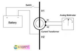
- Connect the galvanometer to secondary terminal –a1/a2/a3 (positive)
- Connect the galvanometer to earth –( negative )
- Apply pulse voltage of 9 V battery to primary + positive and earth negative
- Check the deflection in the galvanometer
- It must be in clock-wise direction
- Above mentioned test to repeated remaining cores
| DO’S | DONT’S |
|
|
Ratio test
- Connect the single phase variac 28 A and step-up transformer230/5000 V
- Connect the step-up transformer across the primary terminals(P1) and earth
- Connect the variac in A.C supply extension board with ELCB rated with 30 mA
- Inject the voltage across the primary terminal and earth
- Note down the corresponding secondary voltage at various cores between phase and earth
- Switch off the supply to the primary injection kit
| DO’S | DONT’S |
|
|
Winding resistance test
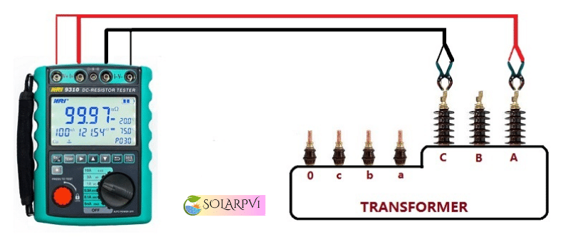
- Connect the multimeter leads to the CVT secondary winding Terminals
- Note down the winding resistance value
- Repeat the above procedure for remaining cores
| DO’S | DON’Ts |
|
|
Continuity test
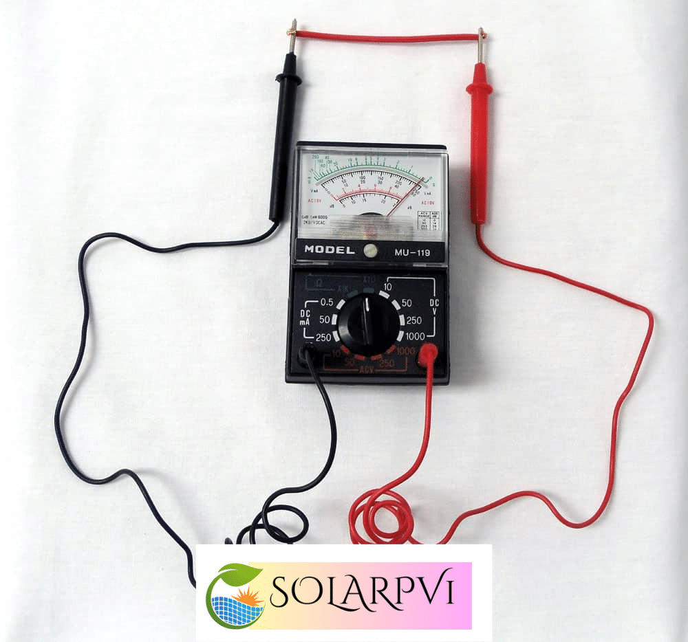
- Connect the multimeter leads to the CVT secondary winding Terminals
- Observe the beep sound in multimeter
- Repeat the above procedure for remaining cores
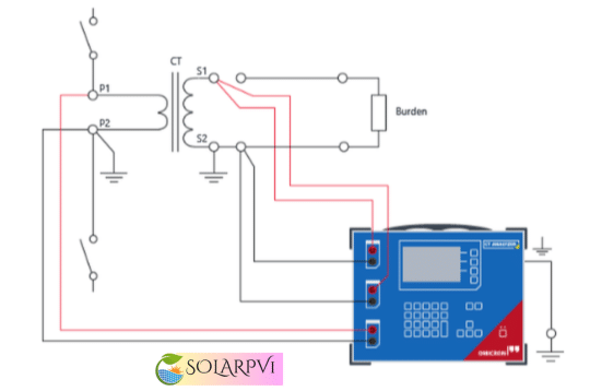
Tan delta test
Top and middle stacks:
- Apply 10 KV between flanges of Top/Bottom stacks
- Carry out measurements in UST mode at 10 KV
Bottom stack connected to EMU PT
- Connect HV of the test kit at the top flange of bottom stack HF point to be grounded Earth connection of the neutral of the PT to be opened/isolated from ground
- Top of CVT to be guarded LV lead of the kit to be connected at the top of the CVT guarding
- Carry out measurements in GST mode at 10 KV
- Repeat the test with neutral of PT connected to ground
- In case Tan delta value negative/erratic only capacitance value are to be monitored
Control Measures
- OCP for IR and Ratio test for CVT is available with testing engineers
- Ensure PTW system in place for the particular bay
- Ensure all supply to the equipment is dead
- Unauthorized persons should not be allowed to enter Testing area
- Barricade the testing area with warning tape
- Proper supervision, conduct job specific toolbox meeting and barricading the entire area
- Calibrated equipment shall be used
- Insulated hand tools shall be used
- Avoid joints for power cable and supply has to be taken via ELCB
- Avoid Lone working
- Use appropriate insulated hand gloves