
Introduction to Electrical Testing
- Electrical testing is a critical aspect of maintaining and ensuring the safety, reliability, and performance of electrical systems. Its primary goal is to identify any defects or issues within these systems before they lead to more significant problems, such as equipment failure, electrical fires, or even personal injury. Understanding the importance of electrical testing is fundamental for everyone involved in the installation, maintenance, and operation of electrical systems.
- There are various scenarios where electrical testing is not just beneficial but essential. For instance, during routine maintenance, electrical testing can help detect early signs of wear and tear, allowing for timely interventions that prevent costly downtimes. Similarly, when troubleshooting electrical issues, testing provides valuable insights into the root causes, facilitating effective and efficient repairs. Moreover, in the context of new installations, electrical testing ensures that all components are correctly installed and functioning as intended, thereby safeguarding the system’s integrity from the outset.
- Despite its importance, inadequate electrical testing is a common oversight that can have severe consequences. Electrical systems that are not thoroughly and regularly tested are more susceptible to failures, which can result in significant financial losses due to equipment damage and operational interruptions. Moreover, the risks extend beyond financial implications; poorly tested electrical systems pose substantial safety hazards. Electrical faults can lead to fires, explosions, and electric shocks, all of which can cause injuries or fatalities.
- Therefore, comprehensive electrical testing is not merely a best practice but a necessity. It provides the assurance that electrical systems are operating optimally and safely, mitigating risks to both property and personnel. By emphasizing the importance of routine and thorough electrical assessments, we can ensure the long-term reliability and safety of our electrical infrastructure.
Insulation Resistance Testing
- Insulation resistance testing is a fundamental aspect of electrical testing aimed at assessing the integrity of insulating materials within electrical equipment and wiring. The primary purpose of this test is to ensure that the insulation can effectively prevent unwanted current flow, which could lead to equipment failure or hazardous conditions such as electrical shocks and fires.
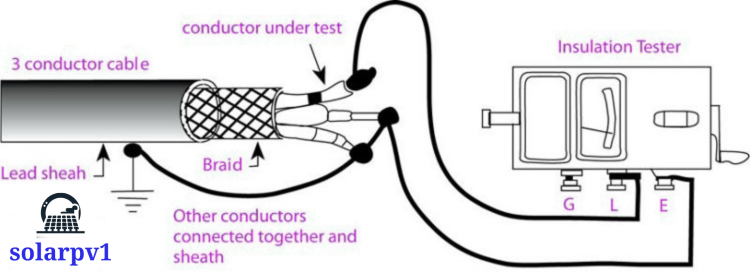
- The most common piece of equipment used for insulation resistance testing is the megohmmeter, often referred to as a “megger.” This device applies a high DC voltage to the insulation and measures the resistance. Adequate insulation will exhibit high resistance values, typically in the range of megaohms (MΩ). The procedure involves connecting the megohmmeter to the electrical system and applying the test voltage, then recording the resistance value displayed on the device.
- The typical steps in insulation resistance testing include de-energizing the equipment, ensuring it is isolated from the power supply, and safely discharging any capacitive energy. Once the equipment is prepared, the megohmmeter is connected, and the test voltage is applied for a specified period. The resistance is then measured and recorded. It is crucial to follow the manufacturer’s guidelines and industry standards during this process to ensure accuracy and safety.
- Interpreting the results of insulation resistance testing involves comparing the measured resistance values against established standards and regulations. Standards such as those set by the International Electrotechnical Commission (IEC) and the National Electrical Code (NEC) provide benchmarks for acceptable resistance levels. Generally, a higher resistance value indicates better insulation quality, while lower values may suggest potential issues such as moisture ingress, aging, or physical damage to the insulation.
- Compliance with these standards is essential for maintaining electrical safety and reliability. Regular insulation resistance testing helps in early detection of insulation deterioration, allowing for timely maintenance and preventing unexpected equipment failures. By adhering to the recommended testing procedures and interpreting the results accurately, electrical professionals can ensure the safe operation of electrical systems and extend the lifespan of electrical equipment.
Continuity and Earth Testing
- Continuity and earth testing are critical components of electrical maintenance and safety protocols. These tests ensure that electrical circuits are complete and that there is a reliable connection to the earth, which is crucial for the safe operation of electrical systems.
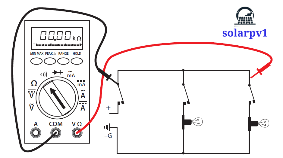
- Continuity testing is used to verify that an electrical circuit is complete, meaning that there is an uninterrupted path for current to flow from the power source to the load and back. This type of testing helps identify open circuits, which can occur due to broken wires, loose connections, or faulty components. To perform a continuity test, technicians use a continuity tester, which typically consists of a battery and a light or buzzer. When the tester is applied to the circuit, a complete path will cause the light to illuminate or the buzzer to sound, indicating that the circuit is intact.
- Earth testing, on the other hand, focuses on the grounding system of an electrical installation. Proper grounding is essential for preventing electrical shock and ensuring the safe operation of electrical equipment. Earth resistance meters are commonly used tools for this purpose. These meters measure the resistance between the earth electrode and the ground, providing valuable information about the effectiveness of the grounding system. A low resistance value indicates a good connection, while a high resistance value may suggest issues such as corroded connections or inadequate grounding.
- The importance of continuity and earth testing cannot be overstated. These tests help prevent potential hazards such as electric shock, equipment malfunction, and even fires. By identifying and addressing issues like poor connections and inadequate grounding, these tests contribute significantly to the overall safety and reliability of electrical systems. Regular testing and maintenance ensure that any problems are detected early and rectified promptly, thereby safeguarding both property and human life.
Advanced Electrical Testing Methods
- Advanced electrical testing methods are essential for diagnosing and evaluating complex electrical systems. These techniques go beyond basic testing to provide deeper insights into system performance and potential issues. Three prominent methods in this category are thermal imaging, harmonic analysis, and power quality analysis.

- Thermal Imaging: Thermal imaging, also known as thermography, utilizes infrared cameras to detect heat emitted by electrical components. This method is particularly useful for identifying overheating components, loose connections, and insulation failures. By capturing thermal images, technicians can visualize temperature differences across electrical systems, enabling them to pinpoint areas of concern before they escalate into major problems. The technology involved in thermal imaging includes high-resolution infrared cameras and sophisticated software for image analysis. Thermal imaging plays a pivotal role in predictive maintenance, allowing for early intervention and thus enhancing system reliability and longevity.

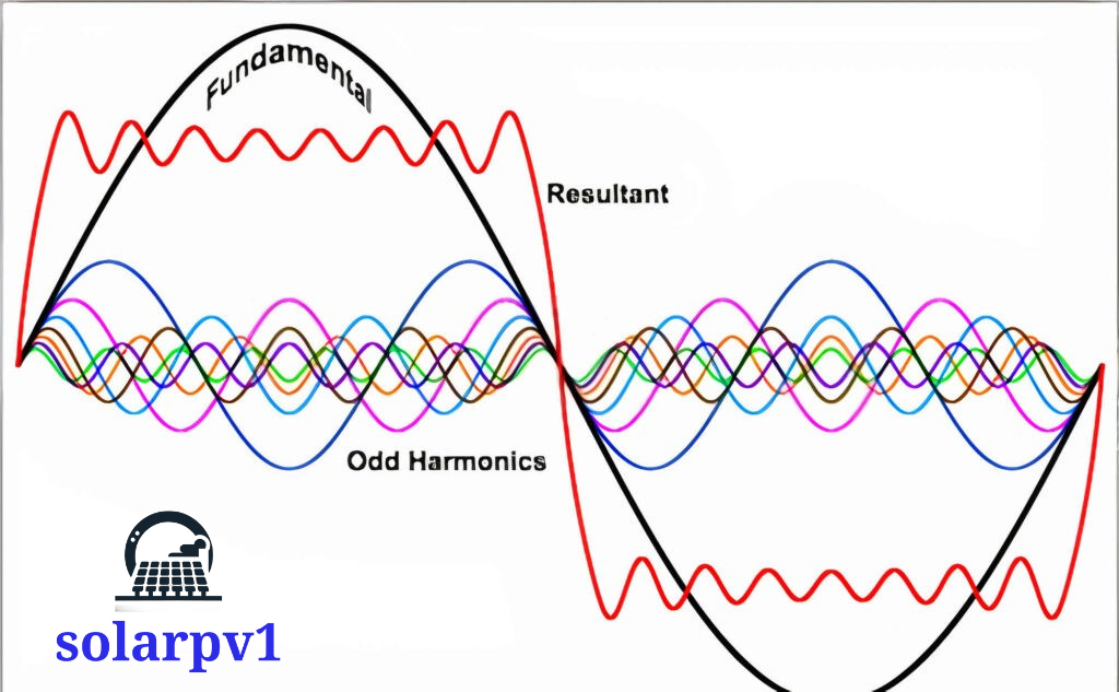
Harmonic Analysis - Harmonic Analysis: Harmonic analysis is used to evaluate the presence of harmonics in electrical systems. Harmonics are voltage or current waveforms that deviate from the fundamental frequency, often caused by non-linear loads such as variable frequency drives and other electronic devices. The presence of harmonics can lead to equipment overheating, reduced efficiency, and even system failures. Harmonic analyzers measure and analyze these distortions, helping to identify their sources and mitigate their impact. By addressing harmonic issues, facilities can improve power quality, ensure compliance with standards, and extend the lifespan of their equipment.

Power Quality Analysis - Power Quality Analysis: Power quality analysis encompasses a broad range of tests designed to assess the health of electrical power systems. This method includes evaluating parameters such as voltage stability, frequency consistency, and the presence of transients or sags. Power quality analyzers are equipped with advanced sensors and data logging capabilities to monitor these parameters in real-time. Poor power quality can result in unexpected downtimes, equipment damage, and increased operational costs. By conducting thorough power quality analysis, organizations can implement corrective measures to maintain optimal system performance and prevent costly disruptions.

- The application of these advanced electrical testing methods is integral to predictive maintenance strategies. Predictive maintenance involves regularly monitoring equipment conditions to predict and prevent failures before they occur.
- By leveraging thermal imaging, harmonic analysis, and power quality analysis, organizations can identify potential issues early, schedule timely maintenance, and avoid unplanned outages. This proactive approach not only enhances system performance but also extends the lifespan of electrical assets, ensuring a more reliable and efficient operation.