
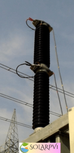
Testing and commissioning of a circuit breaker
Purpose
procedure is prepared to carry out various pre-commissioning tests to be conducted in a systematic dmanner for Circuit Breaker to ensure the healthiness and performance of the equipment
Scope
This procedure covers the Pre commissioning test for Circuit Breaker as for the following
- Insulation resistance of control circuit
- Coil measurement
- DEW point test
- CRM Test
- Timing Test
- Insulation Resistance Test for circuit breaker
Pre-Testing Checks
- Check out the working condition of ELCB(30 mA)
- Check the insulation of power cable for equipment
- Ensure proper earthing and rubber mats available at the work location.
- Calibrated Testing equipment should be used and calibration reports available with engineers for the same
- Check out the insulates hand tools available with the technician
- Ensure the Healthiness of the test leads (Check for any insulation Damages)
- Ensure appropriate PPE’s available at sites
Resources – Tools and Equipment Required
- For IR for control circuit:
- Insulation tester
- Connecting leads
- Coil measurement:
- Multimeter
- Single three pole meter
- Connecting leads
- For CRM Test:
- CRM kit
- Connecting Leads
- Multimeter
- For DEW point:
- Dew point kit
- For Timing Test and coil resistance measurement for circuit breaker:
- Timer Kit
- Test Leads
- Multimeter
- For Insulation Resistance measurement for circuit breaker & control circuit (IR Test):
- Test Leads
- 500 V, 5000 V Insulation Tester
- Insulated Hand Tools
- Multimeter
Operational Sequence of work(Test Procedure)
- Obtain the work permit from the client
- Ensure zero energy in the Circuit Breaker
- Ensure the all connections are in tight before testing
Insulation resistance for control circuit
Control circuit of breakers
- Connect the IR kit across the various points of the control circuit
- Switch ON the IR kit
- Note down the readings
Main circuitof breakers (pole)
- Connect the IR kit across the interrupter while circuit breaker Open condition
- Connect the IR kit across the Pole & Earth while circuit breaker on Close condition
- Switch ON the IR kit
- Note down the readings
Coil Measurement:
TRIP COIL / CLOSE COIL RESISTANCE MEASUREMENT TEST
- Select the Multi meter in Resistance Mode.
- Connect the Multi meter across the Trip/Close coils.
- Note down the readings
OPENING / CLOSING TIME MEASUREMENT TEST
- Connect the Timer across the Breaks for the Opening Time
- Connect the Timer across the Pole for the Closing Time/ “Close-Open” Time
Dew point test:
- Keep breaker off condition
- Connect dew point kit inlet valve to breaker
- Keep outlet valve open condition
- Note down the readings from dew point kit
Contact Resistance Measurement Test:
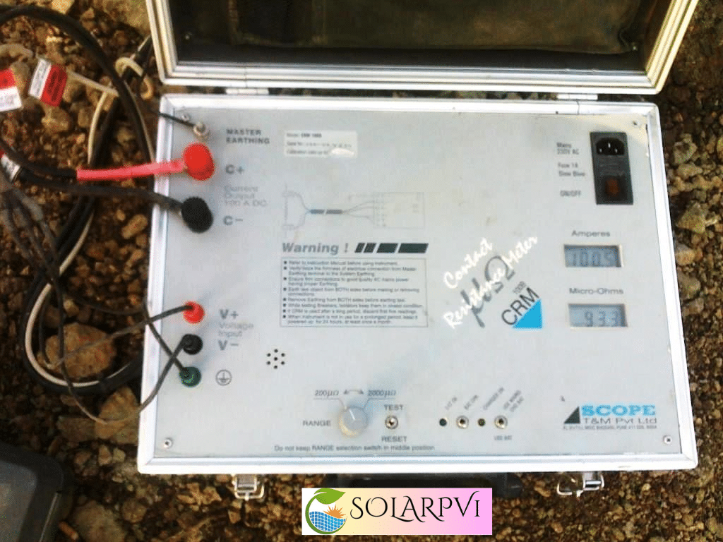
- Keep the Breaker in closed condition
- Connect the earth from CRM kit to earth plate or earth pit
- Connect the CRM kit Current Leads(C+ & C-) across the RØ Circuit Breaker contact
- Then Connect the CRM kit Voltage leads (V+ & V-) across the RØ Circuit Breaker contact. Voltage leads should be connect inside the Current leads
- Connect the CRM kit in A.C supply extension board with ELCB rated with 30 mA
- Inject the rated current to the Circuit Breaker
- Note down the contact resistance value from the CRM kit
- Repeat the above steps for the other phases (YØ & BØ)
- Switch off the power supply to the CRM Kit and disconnect them
| DO’s | DON’TS |
|
|
Timing Test:
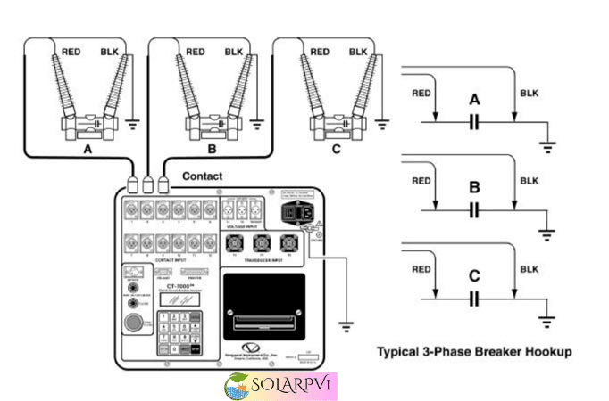
- Keep the Breaker in closed condition
- Connect the earth from Timer kit to earth plate or earth pit
- Connect the Timer kit feedback cables R and R’ leads across the RØ Breaker contact
- Connect the Timer kit feedback cables Y and Y’ leads across the YØ Breaker contact
- Connect the Timer kit feedback cables B and B’ leads across the BØ Breaker contact
- Connect the Timer kit in A.C supply extension board with ELCB rated with 30 mA
- Give The open command and note down the value from the timer kit
- Give the close command and note the value from the timer Kit
- Give the close/open command and note the value from the timer kit
- Switch off the power supply to the Timer Kit and disconnect them
| DO’s | DON’TS |
|
|
Insulation resistance
IR TEST (BREAKER OPEN CONDITION)
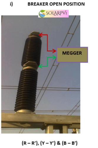
- Keep the Circuit Breaker in open position
- Connect the 5000 V IR kit across the RØ Breaker contact (R & R’)
- Select the required voltage range in 5000 V IR kit
- Switch ON the 5000 V IR kit and press the test button take down the reading
- Repeat the above steps for the other phases (YØ & BØ)
- Discharge the voltage from the Circuit Breaker with respect to earth.
IR TEST BETWEEN PHASE TO EARTH (BREAKER CLOSED CONDITION)
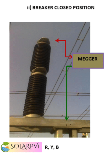
- Keep the Circuit Breaker in closed position
- Connect the 5000 V IR kit Positive lead with RØ Breaker contact
- Connect the 5000 V IR kit Negative lead with earth
- Select the required voltage range in 5000 V IR kit
- Switch ON the 5000 V IR kit and press the test button take down the reading
- Repeat the above steps for the other phases (YØ & BØ)
- Discharge the voltage from the Circuit Breaker with respect to earth.
IR TEST BETWEEN PHASE TO PHASE (BREAKER CLOSED POSITION):
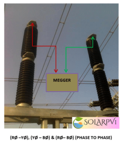
- Keep the Circuit Breaker in closed position
- Connect the 5000 V IR kitPositive lead with RØ Breaker contact
- Connect the 5000 V IR kit Negative lead with BØ Breaker contact
- Select the required voltage range in 5000 V IR kit
- Switch ON the 5000 V IR kit and press the test button take down the reading
- Repeat the above steps for the other phases to phase (RØ-YØ), (YØ & BØ) & (RØ-BØ)
- Discharge the voltage from the Circuit Breaker with respect to earth.
| DO’S | DON’TS |
|
|
Control Measures
- OCP for CRM, Timing and IR test for Circuit Breaker is available with testing engineers
- Ensure PTW system in place for the particular bay
- Ensure all supply to the equipment is dead
- Unauthorized persons should not be allowed to enter Testing area
- Barricade the testing area with warning tape
- More than 2Mtr height shall be used safety belt or full body hardnessand proper working plat form or man lifter
- Less than 2Mtr height shall be used standard insulated ladder
- Inspect the ladders prior to work, keep both feet below 3rd rung from top, keep one hand on ladder minimum at all times.
- Proper supervision, conduct job specific toolbox meeting and barricading the entire area
- Calibrated equipment shall be used
- Insulated hand tools shall be used
- Avoid joints for power cable and supply has to be taken via ELCB
- Avoid Lone working
- Use appropriate insulated hand gloves