
PRE-COMMISSIONING TEST PROCEDURE FOR BUS BAR
This busbar test is prepared to carry out various pre-commissioning tests to be conducted in a systematic manner for Panel Bus bar to ensure the healthiness and performance of the Bus Bar
Scope
This procedure covers the Pre commissioning test for Bus Bar as for the following
- CRM Test
- Insulation Resistance Test
- High Voltage (Hi-Pot)AC Test
Pre-Testing Checks
- Check out the working condition of ELCB(30 mA)
- Check the insulation of power cable for equipment
- Ensure proper earthing and rubber mats available at the work location.
- Calibrated Testing equipment should be used and calibration reports available with engineers for the same
- Check out the insulates hand tools available with the technician
- Ensure the Healthiness of the test leads (Check for any insulation Damages)
- Ensure appropriate PPE’s available at sites
Resources – Tools and Equipment Required
- For CRM Test:
- CRM kit
- Connecting cables
- Insulated Hand tools
- For Insulation Resistance measurement Test (IR Test):
- Test Leads
- 500 V, 5000 V Insulation Tester
- Insulated Hand Tools
- For High voltage Test (Hi-pot test):
- High Voltage Test Kit
- Test Leads
- 500 V, 5000 V Insulation Tester
- Clamp meter
- Insulated Hand Tools
Operational Sequence of work(Test Procedure)
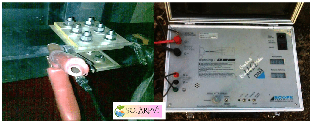
Contact Resistance Measurement (CRM) Test – Bus Bar
- Take the work permit from the client
- Ensure zero energy in the Bus Bar
- Disconnect Bus bar from the transformer
- Connect the earth from CRM kit to earth plate or earth pit
- Connect the CRM kit voltage leads to across the(R-Phase) Bus Bar joint
- Connect the CRM kit current leads to across the(R-Phase) Bus Bar Joint, at the same time Voltage leads should be connected inside the current leads
- Ensure that all the connections are connected properly
- Connect the CRM kit in A.C supply extension board with ELCB rated with 30 mA
- Apply the rated current to the Bus bar
- Note down the resistance value from the CRM kit
- Repeat the above procedures for remaining (YØ & BØ)Phases for CRM Test
- Switch off the supply to the CRM Kit and disconnect the connections
| DO’s | DON’TS |
|
Busbar should be in zero energy condition. Voltage leads should be connected inside the Current leads. While doing this test, no external cables should be connected. Proper grounding should be done for the kit. |
Don’t change the connection sequence (i.e., V+, C+ should be connected to R or Y or B & V-, C- should be connected to R’ or Y’ or B’ ). Don’t change the supply configuration (i.e., voltage should be applied outside the current leads). Contacts should not have any dust during this test. |
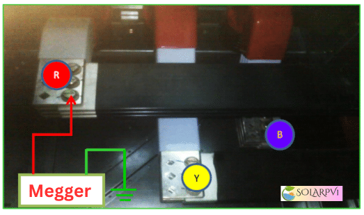
IR TEST BETWEEN PHASE TO EARTH(BUS BAR):
- Check the Bus Bar tightness and panel earthing
- Connect the IR kit Positive lead with RØ Bus Bar
- Then connect the IR kit Negative lead with earth
- Select the required voltage range in IR kit
- Switch “ON” the IR kit and press the test button take down the reading
- Switch “OFF” the IR kit
- Discharge the potential from the bus bar with respect to earth
- Repeat the above steps for the other Bus bar phases (YØ & BØ)
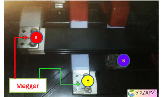
IR TEST BETWEEN PHASE TO PHASE (BUS BAR):
- Connect the IR kitacross the RØ-YØ Bus Bar
- Select the required voltage range in IR kit
- Switch “ON” the IR kit and press the test button take down the reading
- Switch “OFF” the IR kit
- Discharge the potential from the Bus bar with respect to earth
- Repeat the above steps for the other Bus bar phases (YØ-BØ) &( BØ-RØ)
| Do’s | Don’ts |
|
|
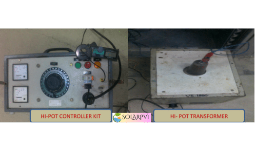
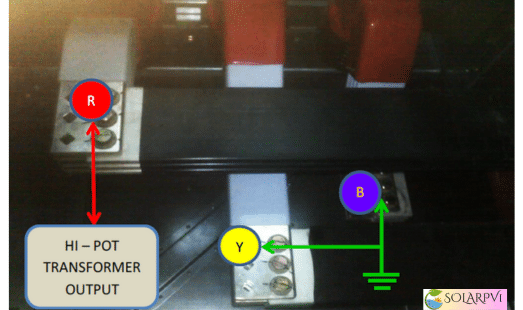
3 High Voltage(Hi-Pot ) AC Test – 11kv Bus Bar:
- Take the work permit from the client
- Check the bus bar terminal should be no voltage and earthing
- Ensure the during the High voltage test all other equipment’s related to the Bus bar installation such as switches, instrument transformers, Cable etc., must be earthed and clearance should be maintained from the other equipment and frame work to prevent flashover.
- Connect the controller kit and Transformer
- Connect the Hi-Pot kit with ELCB 30mA
- Connect the test (Transformer kit)HV lead to the RØ Bus bar conductor
- Looped (Shorted) the other conductors (BØ & YØ) and connect it to the earth
- Switch “ON” the test kit and apply voltage to the Bus bar and after taking the reading
- Switch “OFF” the test kit
- Use discharge rod to discharge the potential from the Bus bar
- Repeat the above steps for measuring the other phases (YØ & BØ)
| Do’s | Don’ts |
|
|