
PRE COMMISSIONING TEST PROCEDURE FOR HT PANEL
This procedure is prepared to carry out various pre- commissioning tests to be conducted in systematic manner for Switch Gear HT Panel to ensure the healthiness and performance of the HT Panel
Scope
This procedure covers the Pre commissioning test for HT Panel as for the following
- CRM Test for Circuit Breaker
- IR Test for Circuit Breaker
- Timer Test for Circuit Breaker
- CRM Test for Bus Bar
- IR Test for Bus Bar
- CT Test
- PT Test
Resources – Tools and Equipment Required
- For CRM Test:
- CRM kit
- Connecting cables
- Insulated Hand tools
- For Insulation Resistance measurement Test (IR Test):
- Test Leads
- 500 V, 5000 V Insulation Tester
- Insulated Hand Tools
- For Timing Measurement Test
- Timer Kit
- Testing leads
- Insulated Hand Tools
- Winding resistance test
- Multimeter with leads
- Polarity test
- 9V battery
- Galvano meter
- Connecting leads
- Ratio test
- Variac / auto transformer
- Step-up Transformer
- Multimeter
- Connecting leads
Operational Sequence of work(Test Procedure)
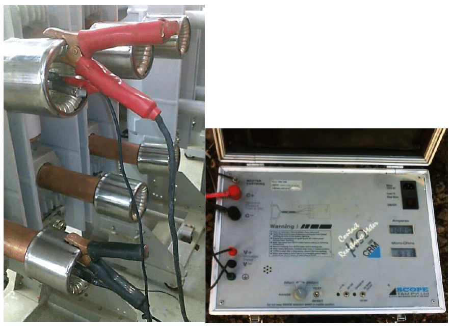
Contact Resistance Measurement Test (Pole to Pole):
- Take the work permit from the client
- Ensure zero energy in the Bus Bar
- Keep the Breaker in closed condition
- Connect the earth from CRM kit to earth plate or earth pit
- Connect the CRM kit Current and Voltage leads across the Breaker contact R & R’
- Connect the CRM kit in A.C supply extension board with ELCB rated with 30 mA
- Inject the rated current to the Circuit Breaker
- Note down the contact resistance value from the CRM kit
- Repeat the above test for another phases (Y & Y’) & (B & B’)
- Switch off the power supply to the CRM Kit and disconnect them
| DO’s | DON’TS |
|
|
IR TEST (BREAKER OPEN CONDITION)
- Keep the Circuit Breaker in open position
- Connect the IR kit across the RØ Breaker contact (R & R’)
- Select the required voltage range in IR kit
- Switch ON the IR kit and press the test button take down the reading
- Repeat the above steps for the other phases (YØ & BØ)
- Discharge the voltage from the Circuit Breaker with respect to earth.
IR TEST BETWEEN PHASE TO EARTH (BREAKER CLOSED CONDITION)
- Keep the Circuit Breaker in closed position
- Connect the IR kit Positive lead with RØ Breaker contact
- Connect the IR kit Negative lead with earth
- Select the required voltage range in IR kit
- Switch ON the IR kit and press the test button take down the reading
- Repeat the above steps for the other phases (YØ & BØ)
- Discharge the potential from the Circuit Breaker with respect to earth.
| DO’S | DON’TS |
|
|
Timing Test for circuit Breaker:
- Keep the Breaker in closed condition
- Connect the earth from Timer kit to earth plate or earth pit
- Connect the Timer kit feedback cables R and R’ leads across the RØ Breaker contact
- Connect the Timer kit feedback cables Y and Y’ leads across the YØ Breaker contact
- Connect the Timer kit feedback cables B and B’ leads across the BØ Breaker contact
- Connect the Timer kit in A.C supply extension board with ELCB rated with 30 mA
- Give The open command and note down the value from the timer kit
- Give the close command and note the value from the timer Kit
- Give the close/open command and note the value from the timer kit
- Switch off the power supply to the Timer Kit and disconnect them
| DO’s | DON’TS |
|
|
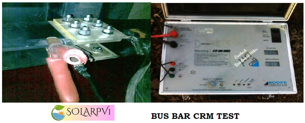
Contact Resistance Measurement (CRM) Test – Bus Bar
- Take the work permit from the client
- Ensure zero energy in the Bus Bar
- Disconnect Bus bar from the transformer
- Connect the earth from CRM kit to earth plate or earth pit
- Connect the CRM kit voltage leads to across the(R-Phase) Bus Bar joint
- connect the CRM kit current leads to across the(R-Phase) Bus Bar Joint, at the same time Voltage leads should be connected inside the current leads
- Ensure that all the connections are connected properly
- Connect the CRM kit in A.C supply extension board with ELCB rated with 30 mA
- Apply the rated current to the Bus bar
- Note down the resistance value from the CRM kit
- Repeat the above procedures for remaining (YØ & BØ)Phases for CRM Test
- Switch off the supply to the CRM Kit and disconnect the connections
| DO’s | DON’TS |
|
|
IR TEST BETWEEN PHASE TO EARTH (BUS BAR):
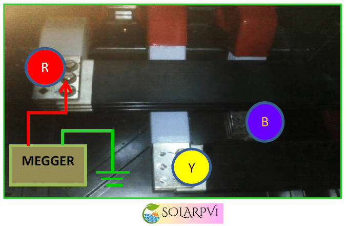
- Check the Bus Bar tightness and panel earthing
- Connect the IR kit Positive lead with RØ Bus Bar
- Then connect the IR kit Negative lead with earth
- Select the required voltage range in IR kit
- Switch “ON” the IR kit and press the test button take down the reading
- Switch “OFF” the IR kit
- Discharge the potential from the bus bar with respect to earth
- Repeat the above steps for the other Bus bar phases (YØ & BØ)
| Do’s | Don’ts |
|
|
IR TEST BETWEEN PHASE TO PHASE (BUS BAR):
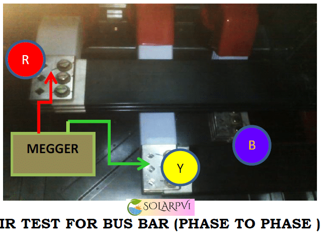
- Connect the IR kitacross the RØ-YØ Bus Bar
- Select the required voltage range in IR kit
- Switch “ON” the IR kit and press the test button take down the reading
- Switch “OFF” the IR kit
- Discharge the potential from the Bus bar with respect to earth
- Repeat the above steps for the other Bus bar phases (YØ-BØ) &( BØ-RØ)
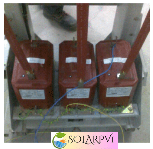
Insulation Resistance (IR) Test for CT Primary to Earth:
- Connect the Earth lead of the IR kit to the earth Terminal
- Connect HV lead of the IR kit to either P1 or P2 of the current Transformer
- Switch “ON” the IR kit and Select the required voltage range in IR kit
- press the Test button take down the readings
- Switch “OFF” the IR kit
Primary to Secondary:
- Connect HV lead of the IR kit to either P1 or P2 of the current Transformer
- Connect Earth lead of the IR kit to either S1 or S2 of the current Transformer
- Switch “ON” the IR kit and Select the required voltage range in IR kit
- press the Test button take down the readings
- Switch “OFF” the IR kit
Secondary to Earth:
- Connect Earth lead of the IR kit to the earth terminal
- Connect HV lead of the IR kit to either S1 or S2 of the current Transformer
- Switch “ON” the IR kit and Select the required voltage range in IR kit
- press the Test button take down the readings
- Switch “OFF” the IR kit
Between Secondary Cores:
- Connect HV lead of the IR kit to either S1 or S2 of the current Transformer
- Connect Earth lead of the IR kit to either S1 or S2 of the other core of the current Transformer
- Switch “ON” the IR kit and Select the required voltage range in IR kit
- press the Test button take down the readings
- Switch “OFF” the IR kit
- Discharge the voltage from the CT with respect to earth.
| DO’S | DON’TS |
|
|
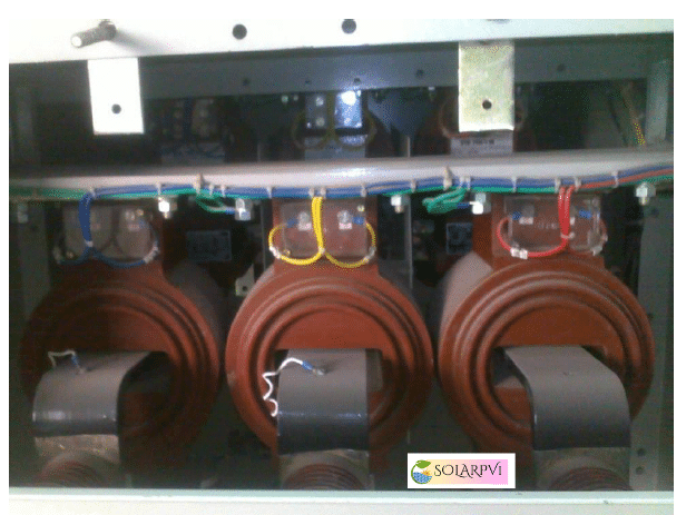
Polarity test for CT:
- Connect the secondary S1 terminal to galvanometer positive terminal and S2 to the negative terminal
- Touch the battery positive terminal to P1 in and negative terminal to the P2 terminal at the CT primary winding Terminals
- Check the deflection in the galvanometer
- It must be in clock-wise direction
| DO’S | DONT’S |
|
|
Ratio test for CT
- Connect the variac and loading transformer
- Connect the loading transformer across the primary terminals(P1,P2)
- Connect the variac in A.C supply extension board With ELCB rated with 30mA
- Short secondary
- Inject the current across the primary terminals.
- Note down the corresponding secondary current at various cores.
- Switch off the supply to the primary injection kit
Winding resistance test for CT
- Connect the multimeter leads to the CT secondary winding Terminals
- Note down the winding resistance value
- Repeat the above procedure for remaining cores
Continuity test for CT
- Connect the multimeter leads to the CT secondary winding Terminals
- Observe the beep sound in multimeter
- Repeat the above procedure for remaining cores
Knee point test for CT:
- Connect the variac to the step-up transformer
- Connect the step-up transformer output to the CT secondary terminal
- Inject the rated voltage to the CT
- Measure the leakage current in that core using leakage current tester with different voltages
- Repeat same procedure to all other core if applicable
Insulation Resistance (IR) Test for PT:
- Connect the IR kit earth lead with earth and connect Positive lead with CVT primary side
- Connect the positive lead to primary and earth lead to secondary each core
- Connect the positive lead to core and earth lead to earth
- Connect the positive lead to any core and earth lead to another core if applicable
- Select the required voltage range in IR kit and apply the voltage to the CVT
- Note the IR values from IR kit
- Discharge the voltage from the CVT with respect to earth.
Polarity test for PT:
- Connect the primary P1 terminal to galvanometer positive terminal and P2 to the negative terminal
- Touch the battery positive terminal to S1 in and negative terminal to the S2 terminal at the CVT secondary winding Terminals
- Check the deflection in the galvanometer
- It must be in clock-wise direction
Ratio test for PT:
- Connect the variac and step-up transformer
- Connect the step-up transformer across the primary terminals(P1,P2)
- Connect the variac in A.C supply extension board with ELCB rated with 30 mA
- Inject the voltage across the primary terminals.
- Note down the corresponding secondary voltage at various cores.
- Switch off the supply to the primary injection kit
| DO’S | DONT’S |
|
|
Winding resistance test for PT:
- Connect the multimeter leads to the CVT secondary winding Terminals
- Note down the winding resistance value
- Repeat the above procedure for remaining cores
| DO’S | DON’Ts |
|
|
Continuity test for PT:
- Connect the multimeter leads to the CVT secondary winding Terminals
- Observe the beep sound in multimeter
- Repeat the above procedure for remaining cores