
Pre-commissioning transformer test
This procedure is prepared to carry out various pre- commissioning tests to be conducted in systematic manner for Transformer to ensure the healthiness and performance of the Device.
Scope
This procedure covers the Pre commissioning test for Transformer as for the following
- Insulation Resistance Test
- Magnetizing current test
- Magnetic core Balance Test
- Vector Group Test
- Ratio Test
- Winding Resistance Test
- Tan Delta Test
- SFRA Test
Tools and Equipment Required
For Insulation resistance test
- IR Kit – 5KV
- Test leads
For Magnetizing Current Test:
- 4 Pole MCB – 2Nos
- Multimeter
- Leakage Tester
- Connecting Cables
- Insulated hand tools
- Test leads
For Magnetic Core Balance Test:
- 4 Pole MCB – 2Nos
- Multimeter
- Connecting Cables
- Insulated hand tools
- Test leads
For Vector Group Test:
- 4 Pole MCB – 2Nos
- Multimeter
- Connecting Cables
- Insulated hand tools
Test leads For Ratio Test:
- 4 Pole MCB – 2Nos
- Multimeter
- Connecting Cables
- Insulated hand tools
- Multimeter with test leads
For winding Resistance Test:
- Transformer winding Resistance Meter
- Test leads
Operational Sequence of work (Test Procedure)
- Obtain the work permit from the client
- Ensure all power to the Transformer is shut down
- Ensure the external wires are removed from Transformer
- Ensure the all connections are in tight before testing
Insulation Resistance (IR) Test:
Primary to Earth:
- Test equipment’s to ensure zero energy state before beginning the work
- Ensure the both side of transformer external connections are removed
- Short all Primary terminals together (1U, 1V,1W) and connect the5000 V IR Kit HV lead to in it
- Connect the 5000 V IR Kit Earth lead with Earth terminal or Earth pit
- Switch “ON” the 5000 V IR Kit and press the Test button take down the readings
- Switch “OFF” the 5000 V IR Kit
- Discharge the potential by using separate earth rod
- Disconnect the all temporary connections
Secondary to Earth:
- Short all secondary terminals together (2U, 2V, 2W) and connect the 5000 V IR Kit HV lead to in it
- Connect the5000 V IR Kit Earth lead with Earth terminal or Earth pit
- Switch “ON” the 5000 V IR Kit and press the Test button take down the readings
Primary to Secondary:
- Short all Primary terminals together (1U, 1V, 1W) and connect the 5000 V IR Kit HV lead to in it
- Short all secondary terminals together (2U, 2V, 2W) and connect the 5000 V IR Kit LV lead to in it
- Switch “ON” the 5000 V IR Kit and press the Test button take down the readings
- Switch “OFF” the 5000 V IR Kit
- Discharge the potential by using separate earth rod
- Disconnect the all temporary connections
Magnetizing Current Test – Transformer
- Take the work permit from the client
- Test equipment’s to ensure zero energy state before beginning the work
- Connect 3Øsupply cable on the HV side (Primary) of the Transformer through 4 Pole MCB-1
- Connect the another 3Ø cable with neutral on the LV side (secondary) of the Transformer through MCB-2
- Switch “ON” the supply of the Primary side (HV) by MCB-1
- Note down the Magnetizing current on the primary side of the Transformer for each phase by using Leakage tester
- Note down the primary side voltage on the MCB-1 by using the
- e. (Across 1U1V, 1V1W, 1W1U)
- Repeat the above steps for all the Tapping’s
- Switch “OFF” the power supply and disconnect
Magnetic core Balance Test:
- Connect 3Øsupply cable on the HV side (Primary) of the Transformer through 4 Pole MCB-1
- Connect the another 3Ø cable with neutral on the LV side (secondary) of the Transformer through MCB-2
- Then remove any one Ø on primary side
- Switch “ON” the supply of the Primary side (HV) by MCB-1
- If R Phase is removed, Measure voltage across (HV)1U1V, 1V1W, & 1W1U in MCB1 & simultaneously (LV) 2U2V, 2V2W, 2W2U, 2U2N, V2N, 2W2N in MCB-2. In this Summation of 1U1V & 1V1W should be equal to 1V1W. 1U1V + 1W1U = 1V1W
Similarly, 2U2V = 2V2W + 2W2U & 2VN = 2U2N + 2W2N in MCB-2
- Note down the readings from Multimeter
- Repeat the above steps for another (Y & B)Phases
- Do the Test for normal tapping. If needed do for 1st& last tapping’s
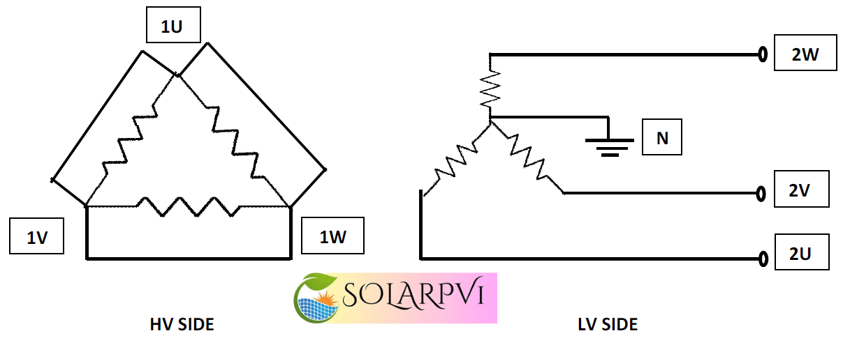
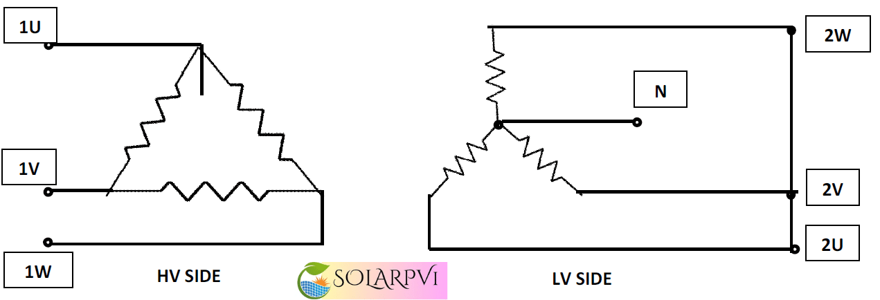
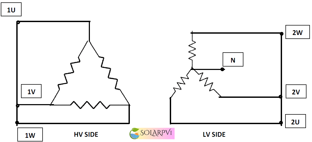
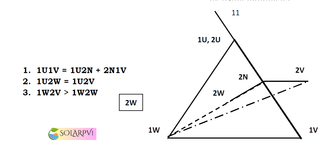
Vector Group Test:
In this Test you have to check the vector group & is the conditions are satisfied.
If Vector Group is Dyn11
- Remove the 2UØ from the Secondary side (LV) i.e. (MCB-2) & connect it along with the (HV) primary side i.e.(MCB-1)1UØ
- Check this condition 1U1V = 1U2N + 1V2N by using multimeter.
- Check the 2nd condition 1U2W = 1U2V
- Check the 3rd 1U, 2U
Winding resistance Test:
HV Side:
- Connect the Winding Resistance Kit Current leads (C+, C-) across the 1U1V of HV side
- Connect the Winding resistance kit Voltage leads (V+, V-) across the 1U1V of HV side. Voltage leads should be connect inside the Current leads
- Connect the Winding resistance kit in A.C supply extension board with ELCB rated with 30 mA
- Switch ON the Kit Note down the Winding resistance value from the Kit
- Repeat the test for all taps provided in the Transformer
- Repeat the above steps for other phases (1V1W & 1W1U)
LV Side:
- Connect the Winding Resistance Kit Current leads (C+, C-) across the 2U2V of LV side
- Connect the Winding resistance kit Voltage leads (V+, V-) across the 2U2V of LV side. Voltage leads should be connect inside the Current leads
- Connect the Winding resistance kit in A.C supply extension board with ELCB rated with 30 mA
- Switch ON the Kit Note down the Winding resistance value from the Kit
- Repeat the test for all taps provided in the Transformer
- Repeat the above steps for other phases (2V2W, 2W2U) & (2U2N,2V2N & 2W2N)
| DO’S | DON’TS |
|
|
Turns Ratio Test:
- Connect the Turns ratio kit HV leads with transformer HV side 1U,1V,1W
- Connect the Turns ratio kit LV leads with transformer LV side 2U,2V,2W & 2N
- Connect the Turns ratio kit in A.C supply extension board with ELCB rated with 30 mA
- Switch ON the Kit Note down the Turns ratio value from the Kit
- Repeat the test for all taps provided in the Transformer
| Do’s | Don’ts |
|
|
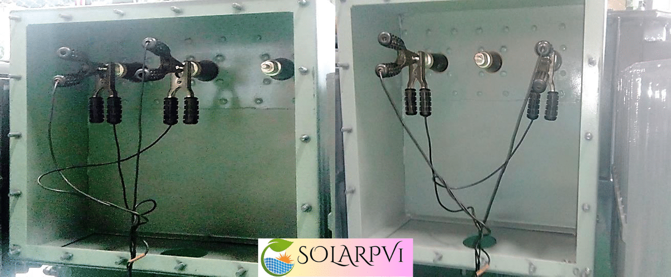
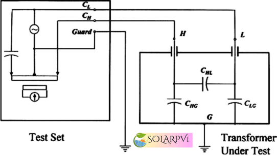
Tan Delta Measurement:
Testing Modes:
UST mode: (Ungrounded specimen test)
GST mode: (Ground specimen test)
Tan Delta Measurement of bushing of transformer is doing in UST mode
Significance of the test
- To determine the deterioration in the insulation of the winding in low, line and higher frequency
- To determine the damages of the dielectric factor in the winding in low, line and higher
- The arithmetic difference in power factors (expressed in %) measured at 10 kV or at the rated maximum line-to-ground voltage before and after dielectric withstand voltage test shall be within the specified limit.
- The % change in capacitance after the dielectric withstand voltage test based on the initial value shall be within thespecified The measurements are to be made at 0 kV or at the rated maximum line-to-ground voltage.
HV Winding Measurement
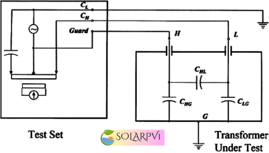
- Short the all Three phases of the HV winding and make the Zero sequence impedance In other words, make the current flow only in Capacitance region (Omit the Inductance)in the impedance network of the transformer.
- Make HV cable connection at HV terminals and LV cable at Neutral (Ground should be isolated).If its delta connection then LV cable connection made in the next
- Select the test mode GST – G for Capacitance measurement in between Tank and the winding; GST – YG for Capacitance measurement in between Windings;
- Apply the 10KV voltage in the stepwise manner and cross check the values in all step
Note the measurement values of Applied Voltage, Leakage Current, Power factor, and Dissipation factor, Capacitance, Humidity and ambient Temperature.
HV- LV CONNECTION
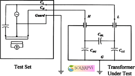
- Short the all Three phases of the HV & LV winding and make the Zero sequence impedance In other words, make the current flow only in Capacitance region (Omit the Inductance)in the impedance network of the transformer.
- Make HV cable connection at HV terminals and LV cable at LV
- Select the test mode UST – YG for Capacitance measurement in between Tank and the winding
- Apply the 10KV voltage in the stepwise manner and cross check the values in all step voltages.
Note the measurement values of Applied Voltage, Leakage Current, Power factor, and Dissipation factor, Capacitance, Humidity and ambient Temperature.
LV- EARTH CONNECTION
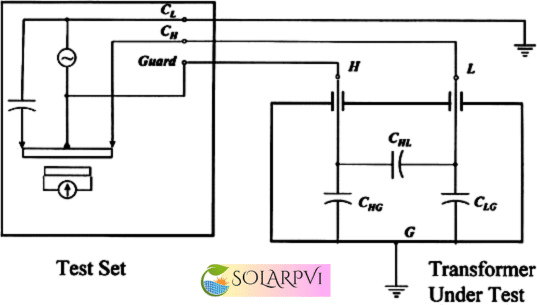
- Short the all Three phases of the LV winding and make the Zero sequence impedance In other words, make the current flow only in Capacitance region (Omit the Inductance)in the impedance network of the transformer.
- Make HV cable connection at LV terminals and LV cable at Neutral (Ground should be isolated). If it’s delta connection then LV cable connection made in the next
- Select the test mode GST – G for Capacitance measurement in between Tank and the winding ; GST – YG for Capacitance measurement in between Windings;
- Apply the 10KV voltage in the stepwise manner and cross check the values in all step
Note the measurement values of Applied Voltage, Leakage Current, Power factor, and Dissipation factor, Capacitance, Humidity and ambient Temperature.
LV-HV CONNECTION
- Short the all Three phases of the LV & HV winding and make the Zero sequence impedance In other words, make the current flow only in Capacitance region (Omit the Inductance)in the impedance network of the transformer.
- Make HV cable connection at LV terminals and HV cable at LV
- Select the test mode UST – YG for Capacitance measurement in between Tank and the winding
- Apply the 10KV voltage in the stepwise manner and cross check the values in all step voltages.
Note the measurement values of Applied Voltage, Leakage Current, Power factor, and Dissipation factor, Capacitance, Humidity and ambient Temperature.
| Do’s | Dont’s |
|
|
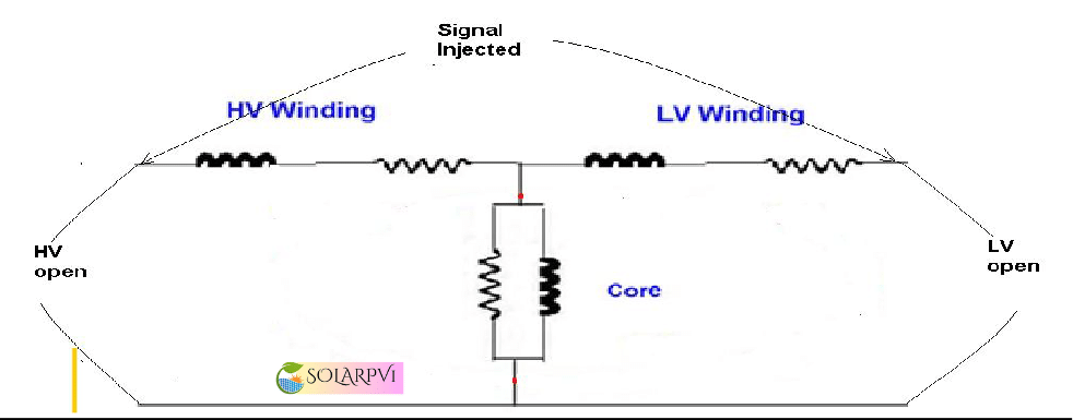
SWEEP FREQUENCY RESPONSE ANALYSIS
HV to Neutral with LV open:
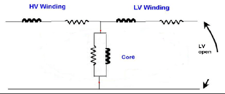
- Feed the frequency signal from 20Hz – 2 MHz in the transformer R ph of the HV winding with respect to the neutral both reference leads should earthed If it is a delta connection, then make the connection of signal injection lead at R phase with respect to the Y phase both reference leads should earthed properly. and kit will receive the response of the impedance characteristic in the transformer.
- Keep the LV winding in open
- Response will be plotted in the logarithmic scaled
- Repeat the all procedures for other phases
HV- Earth With LV shorted
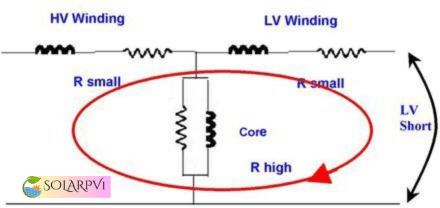
- Feed the frequency signal from 20Hz – 2 MHz in the transformer R ph of the HV winding with respect to the neutral both reference leads should earthed If it is a delta connection, then make the connection of signal injection lead at R phase with espect to the Y phase both reference leads should earthed properly. and kit will receive the response of the impedance characteristic in the transformer.
- Keep the LV winding in shorted (Core is avoided)
- Response will be plotted in the logarithmic scaled graph .
- Repeat the procedure for all other phases
Connection between LV phases with HV opens
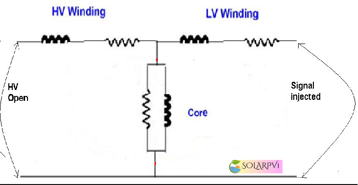
- Feed the frequency signal from 20Hz – 2 MHz in the transformer R ph of the LV winding with respect to the neutral both reference leads should earthed If it is a delta connection, then make the connection of signal injection lead at R phase with respect to the Y phase both reference leads should earthed properly. and kit will receive the response of the impedance characteristic in the transformer.
- Keep the HV winding in open
- Response will be plotted in the logarithmic scaled
- Repeat the procedure for other
Connection Between HV – LV winding
- Feed the frequency signal from 20Hz – 2 MHz in the transformer R ph of the HV winding with respect to LV winding both reference leads should earthed If it is a delta connection, then make the connection of signal injection lead at R phase with respect to the Y phase both reference leads should earthed properly. and kit will receive the response of the impedance characteristic in the transformer.
- Response will be plotted in the logarithmic scaled Repeat the procedure for other phases.
| Do’s | Dont’s |
|
|